PRT Calibration Services
NIST Traceable
ISO/IEC 17025 Accredited
Our lab is accredited by the A2LA to ISO/IEC 17025-2017. Your ISO 9000 (series) or other quality program in most cases recognize this accreditation and can accept our calibrations without the burden of conducting site audits or quality surveys.
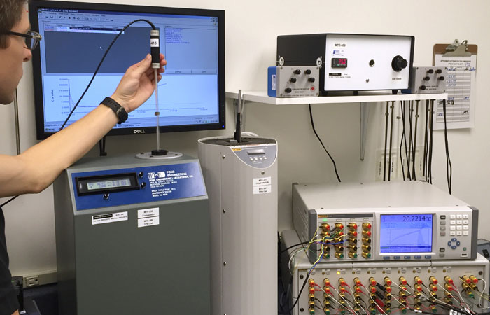
Platinum Resistance Thermometers, or PRTs, are high quality, high precision temperature sensors. The electrical resistance of the platinum sensing element is read by a readout device connected to the sensor. The resistance of the sensor, measured in Ohms, is converted to temperature values by the software of the readout device, using characterization coefficients unique to the sensor, which are resident in the memory of the readout device.
Typical PRT sensor and readout: the Hart 1502A ‘Tweener’ readout and 5615 PRT sensor. The working temperature range of this pair is from approximately -196 °C to 420 °C (328 °F to 1764 °F).
ICL can calibrate the sensor only, using our Hart 1590 Super Thermometer to read it, or we can calibrate the sensor and the client’s readout together for a ‘system calibration’.
What does PRT calibration entail?
Inspection of the sensor: We begin by inspecting the sensor visually; any damage, such as nicks, scratches, dents, or frays in the wires are reported in the ‘Results of Inspection’ section of the report.
An insulation resistance test in accordance with ASTM E-1137 is performed to test the integrity of the internal insulation of the sensor sheath. A minimum resistance of 100 megaOhms is required. The result of this test is also reported.
If you submit your thermometer readout with the sensor for a ‘system calibration’, we perform a check of the accuracy of the readout by connecting the readout to a series of calibrated reference resistors from 10 Ohms to 250 Ohms and comparing the readout’s measured value versus the known value of the reference resistors. We do not charge for this test; it is provided as a courtesy. It is helpful for us as well to have some level of confidence that the readout is working properly.
There are a few thermometer readouts that we cannot test, usually due to cabling or connection issues.
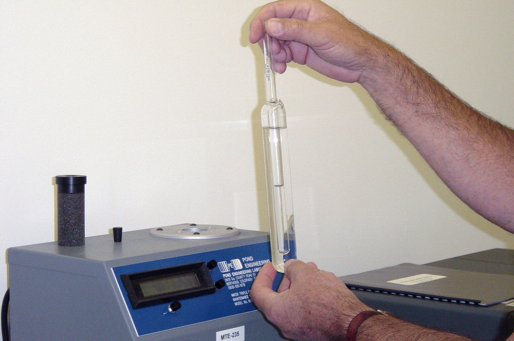
The sensor is tested at the Triple Point of Water. The TPW is an intrinsic temperature point in metrology, realized in a TPW cell with ultra-pure water, where the three phases of water (liquid, solid and vapor) are at equilibrium. The temperature thus produced is defined as 0.010C This value is used as a baseline for the stability of the sensor.
Typically, we are asked to compare your thermometer to NIST traceable calibrated standards at a series of test temperatures, report ‘As Found’ values, and state whether those values are in tolerance or not. If all values are in-tolerance, the calibration is finished and a calibration report is issued.

If the ‘As Found’ values are determined to be out-of-tolerance, there are essentially two options:
- If the change in indication at the triple point of water, 0.01C is modest, typically 0.020C or less, entering the updated, newly observed RTPW (resistance at the triple point of water) into the readout may be all that is required to return the device to in-tolerance condition. Of course all the test points must be repeated using the new RTPW to make this determination. If all ‘As Left’ values are comfortably in-tolerance, the calibration is complete and the calibration report issued.
- If the change in indication is greater, a full recalibration is required.
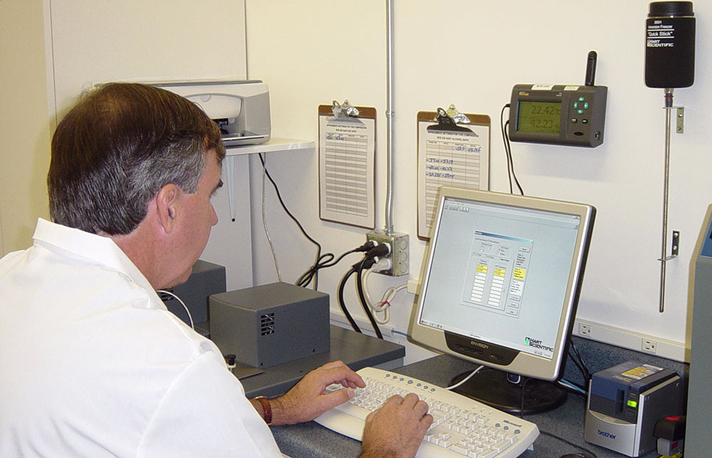
We start with an annealing (heat treating) process to stabilize the sensor, then we subject the sensor to a series of test temperatures across its range. Each test temperature is established in stirred liquid baths monitored by NIST traceable standards. The sensor’s resistance, measured in Ohms, is recorded at each of the test points.
A “typical” PRT working range is from approximately -196C to 420C. Typically we would obtain temperature-resistance data at (approximately) -195, -38.834, 0.01, 200 & 400C.
From the temperature-resistance correlations obtained above, we calculate new ITS-90 calibration coefficients for your sensor. Most commonly used are sub-range 4 (for -190 to 0.01C) and sub-range 8 (from 0.01 to 420C).
In special instances, for example if the client needs to use the device only over a limited range, we will choose calibration temperatures appropriate for that range.
To calculate the new coefficients, we use Hart Scientific’s Tableware software.
Sample Values
Model: Sample
Serial: 1234567
Date: February 22, 2011
TPW:
Reference (C), UUT (Ohms), Residual (C)
0.01, 99.9906, N/A
Low Range:
Reference (C), UUT (Ohms), Residual (C)
-195.654, 20.4179, 0.0000
-38.840, 84.7125, 0.0001
High Range:
Reference (C), UUT (Ohms), Residual (C)
199.993, 175.8044, 0.0001
399.995, 247.0214, 0.0000
Coefficients:
RTPW = 99.9906
Low Range:
a4 = -2.02459019 E-02
b4 = -3.29410408 E-04
High Range:
a8 = -2.03063009 E-02
b8 = -5.45639525 E-05
A final measurement is made at the triple point of water and compared with the value determined at the start of the calibration to check for sensor stability.
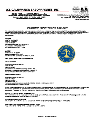
All of this data – ‘As Found’, ‘As Left’, and what was done to get there – including all of the data used for calculation of the new coefficients, is reported to the client by means of the calibration report.
Our charges for this service are competitive, and turnaround times average 5 to 8 working days at our facility.
Calibration order form to send us your device for calibration